A Direct shear test is a laboratory or field test used by geotechnical engineers to measure the shear strength properties of soil or rock material, or of discontinuities in soil or rock masses.
Apparatus
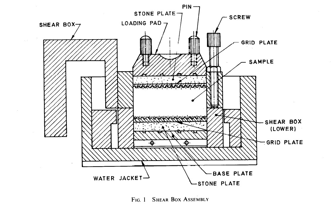
- The shear box grid plates, porous stones, base plates, and loading pad and water jacket shall
- Loading Frame - It shall satisfy the following requirements :
- The vertical stress on the sample shall remain vertical and stand during the test and there shall be arrangement to measure compression.
- The shear stress or strain can be applied in the dividing plane of the two parts of the shear box.
- It shall be possible to maintain a constant rate of increase in stress during the test (irrespective of the strained rate) with arrangement to get different rates of stress increase.
- In case of a strain-controlled apparatus, the strain rate should remain constant irrespective of the stress. Suitable arrangement shall be provided to obtain different strain rates.
- No vibrations should be transmitted to the sample during the test and there should not be any loss of shear force due to friction between the loading frame and the shear box container assembly.
- heights (If Necessary) - for providing the required normal loads
- Proving Ring - Force measuring of suitable capacity, fitted with a dial-gauge accurate to 0.002 mm to measure the shear force.
- Micrometer Dial Gauges - Accurate to 0.01 mm. One suitably mounted to measure horizontal movement and the other suitably mounted to measure the vertical compression of the specimen.
- Sample Trimmer or Core Cutter
- Stop Clock
- Balance - Balance of I kg capacity sensitive to 0.1 g.
- Spatula and a Straightedge
Procedure
-
Undrained Test :
The shear box withthe specimen, plain grid plate over the base plate at the bottom of the specimen and plain grid plate at the top of the specimen should be fitted into position in the load frame. The serrations of the grid plates should be at right angles to the direction of shear. The loading pad should be placed on the top grid plate. The water jacket should be provided
so t,hat the sample does not get dried during the test. The required normal stress should be applied and the rate of longitudinal displacement/shear stress application so adjusted that no drainage can occur
in the sample during the test. The upper part of the shear box should be raised such that a gap of about I mm is left between the two parts of the box. The test may now be conducted by applying horizontal shear load to failure or to 20 percent longitudinal displacement, whichever occurs first. The shear
load readings indicated by the proving ring assembly and the corresponding longitudinal displacements should be noted at regular intervals. If necessary, the varmical compression, if any, of the
soil specimen may be measured to serve as check to ensure that drainage has not taken place from the soil specimen. At the end of the test, the specimen should be removed from the box and the final moisture content measured. A minimum of three (preferably four) tests shall be made on separate specimens of the same density.
-
Consolidated Undrained Test:
The appartus should be assembled in a way similar to that given in Undrained Test except that, instead of the plain grid plates, perforated grid plates and saturated porous stones
should be used at the top and bottom of the specimen. The procedure is same as in Undrained Test except that, after the application of normal stress, the vertical compression of the soil with time should be
recorded. The shear test should be conducted only after complete consolidation has occurred under the particular normal stress. The rate of shear should be such that water does not drain from the specimen at the time of application of the shear load. At the end of the test, the specimen should be removed form the box and the final moisture content measured. A minimum of
three (preferably four) tests should be made on separate specimens of the same density at different normal stresses.
-
Consolidated Drained Test
The shear box with sample and perforated grid plates and porous stones should be fitted into the load frame
After application of normal stress, which is done in increments, the sample should be allowed to consolidate. When the consolidation has completely occured, the shear test should be done at such a slow rate so that at least 95 percent pore pressure dissipation occurred during the
test in this calculated time factor. At the end of the test, the specimen should be removed from the box and the final moisture content
measured. A minimum of three (preferably four) tests should be made on separate specimens of the same density at different normal stresses.
-
The normal stresses to be selected for the test should correspond to the field conditions and design requirements.
Horizontal Load(kg) = Proving Ring Reading * Providing Ring Constant
Corrected Area =
Direct Shear Test is calculated as
Shear Stress(τ) =
Where,
- Ao = Area Of Sample or Intial Area of Speciman in cm2
- δ = Displacement in cm